 Connector Subsea Solutions
 Part of the Subsea Distribution Alliance


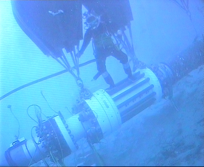
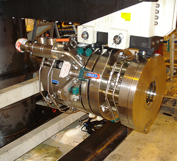
01 // CSS Holdback Clamp as installed
A DEEPWATER PRODUCTION FLOWLINE INSTALLED ON A SLOPE BEGAN ‘WALKING’ UNDER CYCLIC AXIAL LOADING.
CONNECTOR SUBSEA SOLUTIONS (CSS) DEVELOPED A BESPOKE HOLDBACK SYSTEM USING A MORGRIP®
STRUCTURAL CLAMP WITHOUT THE REQUIREMENT FOR INSULATION REMOVAL.
PROJECT BACKGROUND
Pipeline monitoring identified the need for a permanent restraint system near the end terminations of the flowlines at approximately 800 m water depth. If left untreated, the accumulated lateral displacement would continue, increasing pipeline loads in the end termination area.

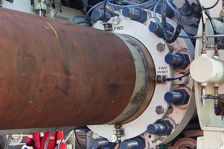
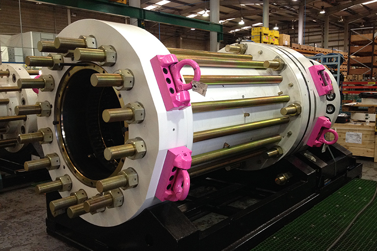
03 // CSS Holdback Clamp during factory acceptance testing (FAT).

02 // ROV inspection of the planned clamp installation location.
PROPOSED SOLUTION
CSS proposed a restraint system comprising of a subsea holdback clamp, tethers and anchor components.
CSS developed the MORGRIP® holdback clamp as a primary load-transfer point, interfacing with tether and suction anchor systems supplied by others.
Following clamp activation onto the pipe, tethers are installed and tensioned between the clamp and anchors to eliminate the risk of walking.
Clamps typically require a bare metal surface to interface with. However, removal of any insulation would result in a local `cold spot’ which would raise flow assurance and corrosion issues. Whilst CSS has proven capability in deepwater coating removal, the client insisted on a solution without coating removal.

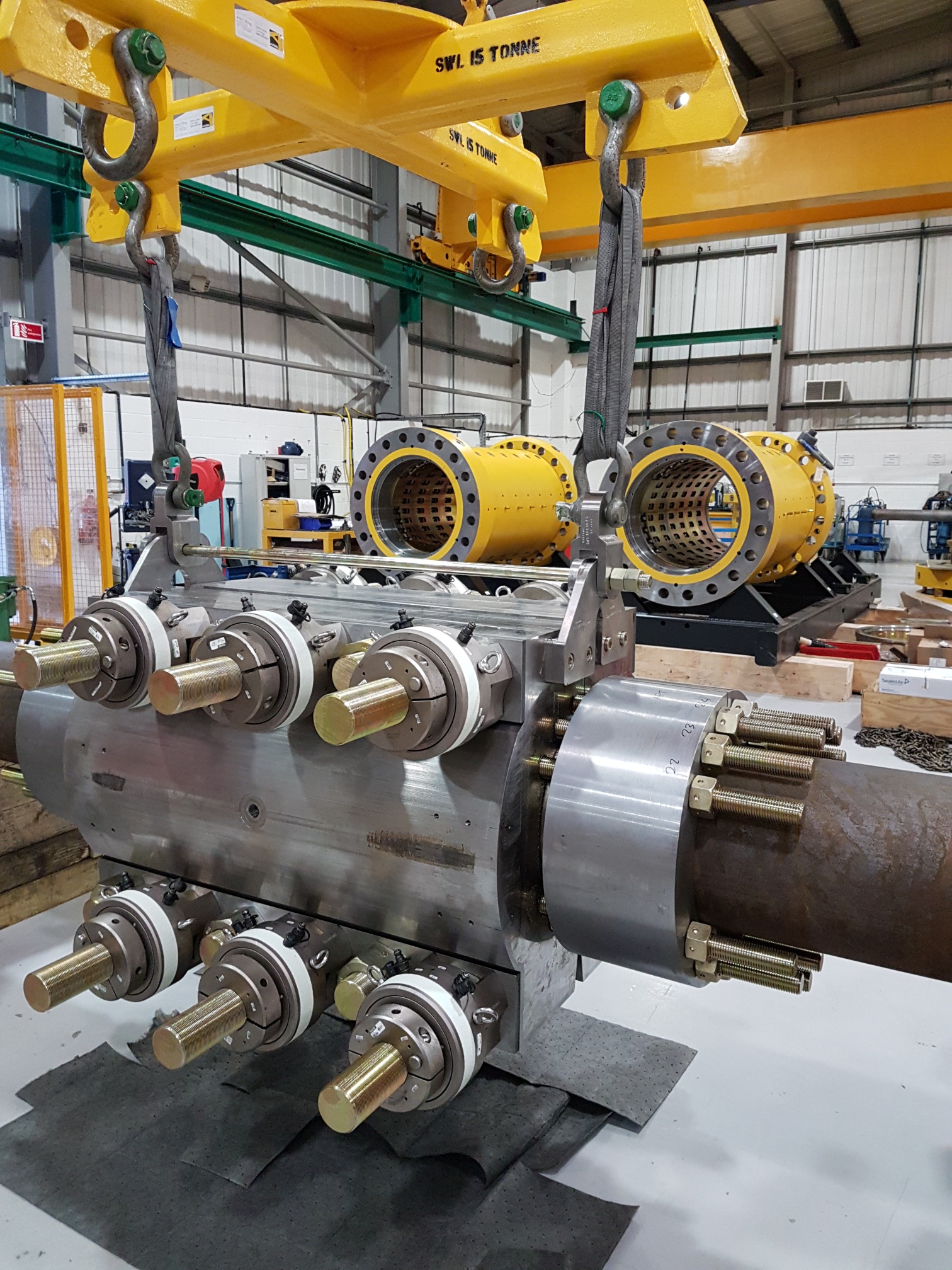
04 // CSS Holdback Clamps post FAT.
PROJECT GOALS AND DELIVERABLES
- Pipeline Walking Restraint: Provide a holdback system to
restrain ‘walking’ loads near the flowline termination. - Load Resistance: Resist axial and lateral loads from the
flowline. - Insulation Grip: Grip directly onto the insulation system to
preserve thermal response and avoid the need for coating
removal. - Controlled Gripping Force: Maintain gripping force over field
life, accommodating coating creep and thermal cycling. - Design Life and Capacity: Meet a 25-year design life and
withstand 280 t axial force.
KEY DESIGN FEATURES:
- Radial Spring Compensation: Springs stacked radially around the clamp circumference, with radial activation of gripping.
- High Coating Confinement: High confinement supports favourable creep behaviour and enables a shorter clamp than bolted flange spring compensation.
- Creep Compensation Capacity: Designed according to client specification and project requirements.
- Hisc Protection and Verification: Sealed spring pockets selected for disc spring protection, using compensators to manage displaced fluid and provide load indication.
- In-Service Inspection Support: Compensator ‘stick-out’ provides indication of applied and remaining gripping force, and confirms spring pocket sealing remains intact.
- Integrated Installation and Activation Tool: Remotely land, position and activate the clamp.

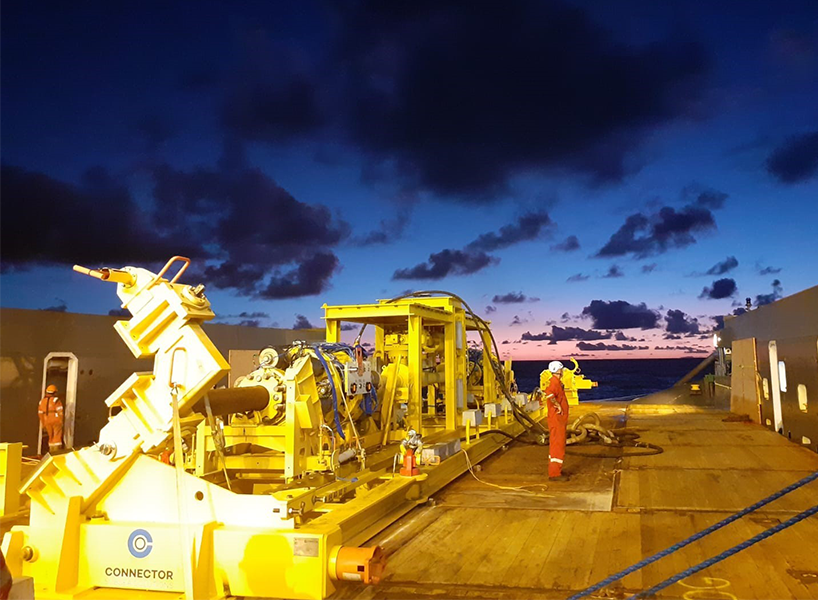
05 // CSS Holdback Clamp and Guide Clamp during installation.

06 // CSS engineer carrying out pre-testing checks on the prototype clamp.
TECHNICAL CHALLENGES AND REQUIREMENTS
- Deepwater Conditions: Restraint required at approximately 800 mwd.
- Seabed Cross Slope: Slope up to 20 ° at the installation location, requiring control of
clamp alignment to avoid skew loading. - Thick Insulation Coating: 63 mm multi-layer thermal insulation with uncertain behaviour under
long-term shear and compression. - Coating Creep: Compensation required to limit loss of gripping force over time.
- Collapse Risk Management: Maximum mechanical clamping pressure limited to 8 MPa.
- End-Of-Life Performance: Loss of clamping pressure limited so final pressure
remains within 50% of initial clamping pressure.
PROTOTYPE TESTING AND VERIFICATION
A simplified full-scale prototype clamp was designed, manufactured and tested to prove the radial spring compensation concept under representative conditions and extreme cases to evaluate design safety factors.
The test programme included short-term creep investigation, axial and radial creep at elevated internal temperature and high tension, temperature cycling, load cycling for ratcheting behaviour, a 280 t load test, and a load test at simulated maximum creep.
Testing was carried out at DNV’s facilities in Bergen, Norway. Cold seawater was pumped from depth in the fjord into a dedicated test tank to replicate subsea conditions at the clamp outer diameter.
An internal test loop with heating and cooling facilitated temperature variation up to 110 °C for accelerated tests. Instrumentation included LVDTs to measure spring compression, coating compression and axial displacement, with monitoring of internal temperature and applied pressures during activation and external tension loading. The test programme ran for approximately one month. The results showed low initial creep, with long-term creep slightly lower than expected. Thermal expansion and contraction effects were larger than anticipated and informed the final
spring system design for the permanent clamps.

06 // CSS Holdback Clamps post FAT.

07 // CSS Holdback Clamp as installed.
OFFSHORE INSTALLATION AND OUTCOME
The holdback system was designed around a 140 t load capacity and validated through load testing to 280 t. Since the pipeline lay on a transverse slope, a purely vertical installation of the main clamp would have introduced skew loading between the clamp, anchor and tensioning system. To avoid this, a separate installation and alignment clamp was deployed to align the main clamp to the seabed before final setup. Two holdback clamp systems were successfully installed in 2020.
LESSONS LEARNED AND CONCLUSIONS
Holding back deepwater pipelines presents a series of technical challenges that must be addressed. This work shows that the traditional approach of gripping directly onto bare steel can be avoided by using radial spring compensation to manage coating creep and maintain controlled load transfer. The design also incorporates HISC protection for the springs using compensators, which support precise load control and provide a practical means of in-service inspection to confirm that gripping and spring protection remain effective.